
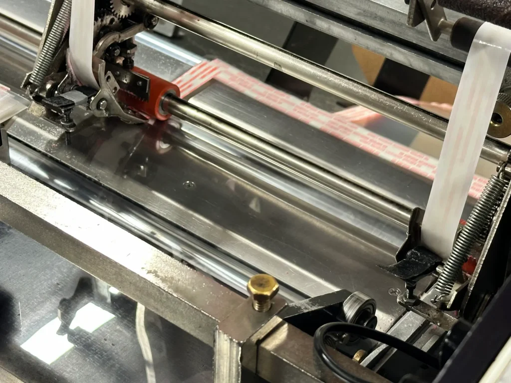
Die cutting uses a precision-shaped die to cut materials at exact tolerances, repeatably and at scale. This guide covers:
Die Cutting Techniques
Choosing the right technique starts with your material. Design complexity and production volume determine what comes next.
Rotary Die Cutting
Rotary die cutting mounts cylindrical dies on rotating rollers. Material feeds through the machine continuously while the dies cut shapes at speeds up to 40,000 units per hour. Each pass runs multiple operations simultaneously, eliminating additional processing steps:
- Cutting
- Laminating
- Slitting
Rotary die cutting achieves tolerances as tight as ±0.005 inches. It works best for thin, flexible substrates under 0.015 inches:
- Films
- Foams
- Tapes and adhesives
Flatbed Die Cutting
Flatbed die cutting presses a flat die onto sheet material in a start-stop cycle. It handles thicker, more rigid substrates that rotary cutting cannot accommodate:
- Rubber
- Foam
- Rigid composites
- Certain metals
Flatbed supports material widths up to 40 inches at tolerances of ±0.010 inches. Production capacity runs 2,000 to 4,000 parts per hour depending on part size.
Steel Rule Die Cutting
Steel rule die cutting shapes a steel blade into your design profile, embeds it in a wood or metal base, and presses it against the material. It suits new designs and lower-volume runs, particularly those with straightforward geometries. Average tooling cost runs $100 to $500, compared to $500 to $2,000 for rotary tooling. This cost difference makes steel rule the practical starting point for prototypes.
Kiss Cutting
Kiss cutting scores material to a precise depth without cutting through the backing layer. It applies to any adhesive part that requires clean separation from the liner, including labels and peel-and-stick gaskets.
Matching Your Material to the Right Method
Material type dictates the cutting method and the tolerances achievable.
| Material | Preferred Method | Common Applications |
|---|---|---|
| Plastics (PET, PVC, Polycarbonate) | Flatbed (thick sheets) / Rotary (films under 0.015″) |
|
| Foams (Open-cell & Closed-cell) | Rotary (thin gaskets) / Flatbed (thick padding) |
|
| Rubber (Neoprene, EPDM, Silicone) | Flatbed (thick sheets) / Rotary (thin seals) |
|
| Paper & Cardstock | Rotary (high-speed) / Flatbed (specialty) |
|
| Tapes & Adhesives | Rotary (roll-to-roll) |
|
| Metal Foils (Aluminum, Copper at or under 0.015″) | Rotary (ultra-thin) / Flatbed (slightly thicker) |
|
Three additional factors determine which method fits your project:
- Tolerances: Rubber and foam compress under load. Tighter process control maintains dimensional accuracy.
- Adhesive backings: Tapes and films with adhesives affect liner selection and kiss-cut performance.
- Durability requirements: Aerospace and medical components demand materials with high resilience under load.
The Die Cutting Process: Step by Step
A successful die cutting project starts with careful design and ends with quality-checked, production-ready parts. Here’s what happens at each stage.
| Step | What Happens | Key Activities |
|---|---|---|
| 1. Design | The team reviews your specifications and prepares the design for production. Engineers build or refine a prototype and test it functionally before moving forward. |
|
| 2. Die Creation | Die toolers fabricate the die from high-grade steel, focusing on sharpness and dimensional accuracy for reliable performance throughout the production run. |
|
| 3. Machine Setup | The operator mounts the die, calibrates pressure, and aligns the material. CAM (computer-aided manufacturing) software establishes tight tolerances and helps minimize material waste from the first cycle. |
|
| 4. Quality Approval | Initial samples undergo QMS (quality management system) review before full production. Customers may also test samples at this stage. |
|
| 5. Production | The die cuts the desired shape from the material. Rotary lines run continuously, while flatbed presses operate in cycles. In-process checks maintain consistency throughout the production run. |
|
| 6. Post-Processing | Cut parts are de-nested and undergo any required finishing. Excess material is collected and reclaimed where possible. |
|
Colvin Friedman’s Production Capabilities
Colvin Friedman has operated rotary and flatbed die cutting lines from its Petaluma, California facility since 1949.
| Category | Rotary | Flatbed |
|---|---|---|
| Maximum Product Width | 16 inches (larger jumbos slit down) | 40 inches |
| Maximum Product Thickness | 0.015 inches | 0.5 inches |
| Tolerance Level | ±0.005 inches | ±0.010 inches |
| Maximum Production Capacity | 40,000 units/hour | 2,000–4,000 parts/hour |
| Average Lead Time | 3 weeks | 3 weeks |
| Average Initial Tooling Cost | $500–$2,000 | $100–$500 |
To confirm which process fits your project, contact Vice President Josh Rodman at (707) 769-4488 or request a quote online.
Request a QuoteDie Cutting vs. Other Cutting Solutions
Die cutting isn’t the right solution for every application, but for many thin-material, high-volume projects, it offers advantages over alternative cutting technologies.
| Alternative | Why Die Cutting Wins | Example Application |
|---|---|---|
| Laser Cutting | Faster and more cost-effective for high-volume runs | Automotive gaskets: Die cutting can outperform laser cutting in speed and material efficiency. |
| Waterjet Cutting | More efficient for thin, non-metallic materials | Disposable filtration media: Die cutting delivers consistent output at high volume. |
| CNC Routing | Better suited to large-batch production of thin, flat materials | Electronic insulation films: Die cutting delivers fast, high-precision cuts with minimal tool wear. |
| Plasma Cutting | Ideal for non-metallic substrates, while plasma excels at thick metals | Foam cushioning inserts: Die cutting handles various foam densities at production speed. |
Further Reading
- Rotary Die Cutting: Full specifications and capabilities
- Flatbed Die Cutting: When to choose flatbed over rotary
- Steel Rule Die Cutting: Cost-effective cutting for simpler geometries
- Custom Die Cutting: Colvin Friedman’s full process from consultation to production
- Die Cutting vs. Laser Cutting: A side-by-side comparison of both methods